
Views: 0 Author: Site Editor Publish Time: 2026-08-24 Origin: Site


In demanding semiconductor manufacturing environments like Epitaxy, MOCVD, and RTP, component integrity directly dictates wafer yield. SiC coated graphite delivers exceptional thermal stability and robust chemical resistance, making it an indispensable material for these high-temperature processes. However, operators often underestimate the extreme mechanical fragility of these high-performance materials. Improper handling or overly aggressive cleaning cycles can easily compromise the thin protective layer, exposing the highly porous graphite substrate underneath.
Once exposed, this substrate acts as a severe contamination source within the process chamber. It triggers immediate carbon dusting, severe outgassing, and ultimately, catastrophic yield losses across the wafer lot. Fabs must actively address this handling vulnerability to sustain high production standards and protect expensive epitaxial layers.
This guide provides an evidence-based framework for managing these critical consumables. We will explore safe handling protocols, evaluate advanced cleaning methodologies, and compare in-house versus outsourced processing models. You will learn how to optimize component lifecycles, preserve the delicate coating, and maximize returns without risking dangerous wafer contamination.
Mechanical Fragility vs. Chemical Durability: The SiC layer is highly resistant to chemicals but exceptionally brittle; mechanical shock during handling is the leading cause of premature failure.
Cleaning Method Selection: Advanced fabs are shifting toward precision megasonic cleaning combined with targeted chemical baths to remove process deposits without eroding the SiC layer.
Lifecycle Economics: Outsourcing cleaning to specialized service providers often yields better coating preservation than relying on standard in-house wet benches, depending on the fab’s volume and process complexity.
Inspection is Critical: Post-cleaning metrology must actively screen for micro-cracks and pinholes; visual inspection alone is insufficient for decision-stage lifecycle management.
Contamination stemming from compromised Semiconductor Graphite Parts directly correlates to increased defect density in epitaxial layers. Process engineers face a constant battle against particulate generation. The primary business goal here is to extend part lifespan while maintaining strict zero-particle success criteria within the reactor. Failing to do so results in scrapped wafers, wasted precursor gases, and severe blows to overall fab profitability.
We often refer to this failure mode as the "killer defect" mechanism. The chemical vapor deposition (CVD) process used to apply the silicon carbide layer creates a dense, protective barrier. However, if handling induces microscopic cracks, the barrier fails. These micro-cracks allow process gases or highly reactive cleaning chemicals to seep through the barrier and aggressively attack the underlying graphite substrate. As the graphite oxidizes or dissolves, sub-surface voids form. This eventually leads to sudden, catastrophic delamination of the coating during a high-temperature run, showering the wafer with lethal particulate matter.
High-purity susceptors, wafer carriers, and support trays represent high-CAPEX consumables. A typical advanced epitaxy reactor utilizes dozens of these precision components, each costing thousands of dollars. Reducing cleaning-induced damage by even 15% translates to significant annual procurement savings. Fabs optimizing their handling protocols see an immediate reduction in consumable spend. More importantly, they avoid the hidden costs of unexpected tool downtime and lengthy chamber recovery baked into catastrophic part failures.
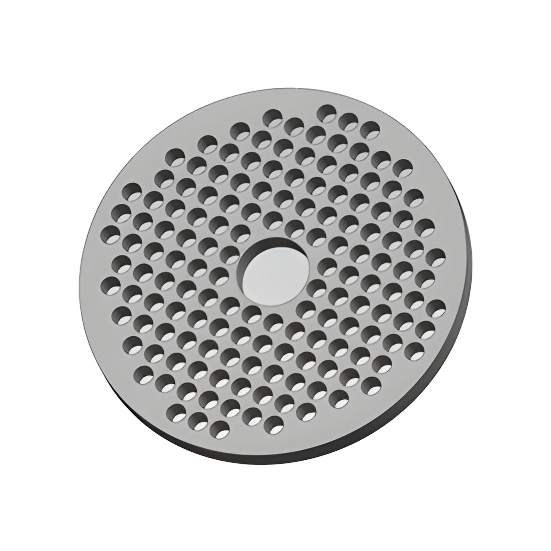
Process engineers must acknowledge harsh implementation realities. SiC coatings applied to graphite are typically only 50 to 100 microns thick. While incredibly hard, this thin layer behaves like glass. Standard cleanroom handling procedures simply do not offer enough protection. Fabs must heavily modify their standard operating procedures specifically for these unique components.
Physical transport remains the highest-risk activity for component failure. Bumping a tray against a quartz tube or dropping it merely a few millimeters onto a hard bench can instantly shatter the local coating. To mitigate these risks, fabs should implement strict physical transport and shock prevention rules.
Mandate dedicated carrier boxes: Always transport components in custom-molded, padded carrier boxes. Never carry an exposed susceptor across the cleanroom bay.
Prohibit component stacking: Never stack coated graphite parts on top of one another. The hard SiC surfaces will grind against each other, initiating microscopic surface fractures.
Eliminate metal-to-SiC contact: Standard stainless steel tweezers will scratch the coating. Operators must use only Teflon-coated or PEEK-coated tongs when moving these items into the reactor or cleaning bath.
Contamination avoidance represents the second critical pillar of handling. Human interaction introduces organics and moisture, both of which severely degrade high-temperature performance.
Strict glove requirements: Operators must wear specific, high-purity cleanroom gloves. Standard latex or nitrile can leave organic residues. At 1200°C, a microscopic organic fingerprint turns into localized ash. This creates a thermal hotspot that forces the coating to crack under stress.
Controlled storage environments: Always store clean parts in N2 purged dry cabinets. The microscopic surface anomalies of SiC can trap ambient cleanroom humidity. If operators place a moisture-laden part into a rapid thermal processing (RTP) chamber, the trapped water violently boils off, blowing microscopic holes through the protective layer.
After a process run, operators must remove polysilicon, silicon nitride, or silicon dioxide build-ups from SiC Coated Graphite Parts. Selecting the right solution category determines the survival rate of your consumables. Below, we compare the standard approaches used across the industry.
Table: Comparison of Primary Cleaning Methodologies
Cleaning Method | Primary Mechanism | Key Advantages | Inherent Risks |
|---|---|---|---|
Chemical Bath (Wet Etch) | Acid dissolution (HF, HNO3) | Highly effective at stripping thick silicon/oxide deposits. | High risk of substrate erosion if pinholes exist. |
Megasonic Cleaning | High-frequency acoustic cavitation | Zero mechanical stress; removes sub-micron particles safely. | Requires specialized, high-cost acoustic equipment. |
Thermal Bake-Out | High-temperature vacuum outgassing | Vaporizes trapped volatile organics and moisture. | Thermal shock can cause delamination if ramp rates are too fast. |
Chemical bath cleaning remains a staple in most wet process areas. Fabs typically evaluate the efficacy of mixed acid solutions, such as combinations of Nitric Acid (HNO3) and Hydrofluoric Acid (HF). HNO3 aggressively oxidizes silicon deposits, while HF strips away oxides. Fortunately, pristine SiC remains completely inert to HF. However, the evaluation dimension shifts dramatically when considering chemical penetration risks. If the coating contains even a single microscopic pinhole, HF will aggressively seep through. Once inside, it rapidly erodes the porous graphite substrate, hollowing out the component from the inside without changing its outward appearance.
To safely remove stubborn particulate matter, advanced fabs utilize precision megasonic cleaning. Megasonic systems operate at frequencies near 1 MHz. This high-frequency energy creates gentle acoustic streaming and microscopic cavitation bubbles. It removes sub-micron particles with near-zero mechanical stress. This drastically mitigates the risk of micro-crack propagation inherent in standard ultrasonic cleaning. Ultrasonic baths operate at lower frequencies (20-40 kHz), creating large, violent cavitation bubbles that frequently chip brittle SiC coatings.
After wet cleaning, thermal bake-outs provide the final decontamination step. Fabs perform high-temperature vacuum baking to outgas any volatile contaminants or moisture trapped during the wet-clean cycle. Operators must carefully manage the temperature ramp rates during this step. Heating the parts too rapidly causes uneven thermal expansion between the coating and the substrate, leading to instantaneous cracking.
Ultimately, fab managers must adopt a philosophy of trust and verification. Acknowledge that every cleaning cycle inherently causes micro-wear. The objective is controlled, predictable degradation, not the illusion of infinite part life. By balancing chemical action with gentle megasonic energy, you can significantly prolong the functional utility of your graphite investments.
Determining whether to clean process components internally or utilize external vendors involves a complex evaluation framework. Fab managers must weigh cycle times, capital expenditures, and process control when deciding between internal processing and third-party vendor services.
In-house processing appeals to fabs demanding absolute control over their supply chain. The pros of this approach include substantially lower cycle times. You can remove a dirty susceptor, clean it, bake it, and return it to the epitaxy tool within 24 hours. Furthermore, internal processing maintains complete chain-of-custody control and eliminates the physical shock risks associated with shipping fragile parts off-site.
However, the cons of in-house processing are steep. Establishing a dedicated, contamination-free wet bench requires a massive capital investment. SiC coated parts require specific chemical lines, automated hoists, and ultra-pure water (UPW) rinses separate from standard wafer processing tools. Additionally, your facility team must manage the highly toxic chemical disposal streams generated by large-volume HF and HNO3 baths, increasing environmental health and safety (EHS) overhead.
Outsourced cleaning and refurbishment offers a compelling alternative for many modern semiconductor facilities. Specialized vendors bring immense technical advantages. The pros include access to proprietary restoration techniques. Some advanced vendors can execute localized chemical vapor deposition (CVD) patching, effectively restoring minor coating defects and preventing part scrapping. Furthermore, specialized vendors already own industrial-scale megasonic equipment and advanced metrology tools that most fabs cannot justify purchasing just for consumable maintenance.
The primary cons of outsourcing center around logistics. Utilizing external vendors requires increased inventory levels. Fabs must procure additional susceptors to account for transit and processing lead times, which often stretch to several weeks. Shipping also introduces vibration risks, mandating expensive, specialized suspension packaging.
Fabs should apply practical shortlisting logic when making this decision. Facilities running high-volume standard logic or memory devices may prefer outsourced bulk cleaning to keep their internal floor space dedicated to revenue-generating wafer tools. Conversely, specialized R&D fabs, or power-device manufacturers handling custom-machined SiC susceptors for GaN or SiC epitaxy, may require the strict intellectual property security and fast turnarounds of in-house control.
Cleaning the component only solves half the problem. Defining strict success criteria for re-integration dictates how you verify a part is genuinely safe to return to the process chamber. Skipping rigorous post-clean metrology guarantees eventual wafer contamination.
Modern defect detection strategies must move far beyond standard visual inspection. To the naked eye, a severely compromised susceptor often looks identical to a brand-new one. Instead, engineers must deploy microscopic imaging to scan high-stress areas, such as wafer pocket edges and lift-pin holes, for hairline fractures.
Weight-loss tracking serves as the most reliable indicator of hidden structural failure. Technicians weigh the component precisely before its first use and track its mass after every cleaning cycle. The SiC coating itself barely degrades during an HF wet etch. Therefore, if the part registers a sudden or steady drop in weight, it strongly indicates that acid has breached a pinhole and is actively etching away the internal graphite mass.
Surface Roughness (Ra) Profiling: Over dozens of thermal and chemical cycles, the previously smooth SiC surface inevitably roughens. Profiling the Ra value helps engineers predict when the surface will become too textured to support uniform epitaxial gas flow.
Optical Microscopy: Technicians inspect the physical edges of the component under high magnification, searching for localized chipping caused by handling errors.
Dimensional Tolerance Checks: Ensuring the wafer pockets have not warped due to repeated thermal cycling, which would cause poor thermal transfer to the wafer.
Effective End-of-Life (EOL) decision logic removes emotion from the disposal process. Engineering teams must define clear, mathematical thresholds for part retirement. A fab might establish a rule retiring any component exhibiting a 0.5% total weight loss, visible edge chipping larger than 2 millimeters, or specific localized coating thinning detected via ultrasonic thickness gauges.
Holding onto degrading components to save procurement budgets represents a false economy. Retiring a part early is mathematically much cheaper than suffering a scrapped wafer lot. A single batch of advanced power semiconductor wafers holds substantially more value than the cost of a replacement graphite susceptor.
Maximizing the return on investment for SiC coated graphite requires treating handling and cleaning not as an afterthought, but as a highly controlled sub-process of daily fab operations. These components form the thermal and chemical foundation of your most sensitive deposition processes. Recognizing their mechanical fragility and implementing rigid transport, cleaning, and metrology standards will drastically reduce particle generation and extend component life.
As immediate next-step actions, we recommend process engineers audit their current wet-bench standard operating procedures (SOPs) explicitly for graphite parts. Ensure operators are not treating them like standard quartzware. Assess the feasibility of installing megasonic upgrades to replace destructive ultrasonic tanks. Finally, if you outsource your maintenance, request detailed degradation and metrology reports from your cleaning vendors to better track the true lifecycle of your critical process hardware.
A: Yes, SiC is highly resistant to HF, making it effective for removing silicon or oxide deposits. However, if the coating has micro-cracks or pinholes, HF will aggressively attack the underlying graphite substrate. Thorough inspection prior to chemical baths is mandatory.
A: Ultrasonic cleaning uses lower frequencies that create larger, more destructive cavitation bubbles, which can chip brittle SiC coatings. Megasonic cleaning operates at much higher frequencies, creating gentler, microscopic cavitation ideal for removing sub-micron particles without damaging the part.
A: There is no universal number; it depends heavily on the thickness of the initial coating, the aggressiveness of the epitaxial deposits being removed, and the exact cleaning chemistry used. Lifecycle is typically tracked by dimensional tolerance changes and weight variance rather than purely by cycle count.


